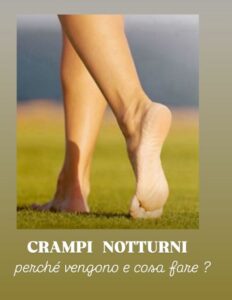
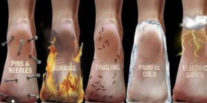
Chuột rút ban đêm (thường gặp nhất là chuột rút chân về đêm ) là những cơn co thắt cơ không tự chủ đột ngột, đau đớn xảy ra ở bắp chân, bàn chân hoặc đùi khi bạn đang ngủ. Trong hầu hết các trường hợp, không có nguyên nhân cụ thể nào được biết đến — chúng có thể là do cơ bắp mệt mỏi và các vấn đề về thần kinh.
Lý do họ đến (nguyên nhân và yếu tố kích hoạt phổ biến)
Tuổi tác làm tăng nguy cơ, nhưng chuột rút thường xảy ra mà không rõ nguyên nhân .
Nên làm gì khi bị chuột rút (cách giảm đau tức thì)
-
Giãn cơ mạnh : Gập mu bàn chân lên phía mặt (gập mu bàn chân) – đây là cách hiệu quả nhất để giảm chuột rút bắp chân.
-
Đứng và gập đầu gối : Nếu bạn có thể đứng, hãy dồn trọng lượng lên chân bị chuột rút và hơi gập đầu gối.
-
Mát-xa nhẹ nhàng : Xoa bóp vùng cơ bị co cứng để giúp thư giãn.
-
Áp dụng nhiệt hoặc lạnh :
-
Đắp đá/túi lạnh trực tiếp lên vùng bị đau để giảm đau.
-
Dùng khăn ấm, miếng đệm nhiệt, tắm nước nóng hoặc tắm vòi sen nước nóng hướng vào vùng cơ để thư giãn các cơ bị căng cứng.
-
-
Đi bộ hoặc lắc chân : Vận động nhẹ nhàng có thể giúp cơ bắp được thư giãn.
Cách phòng ngừa chuột rút ban đêm
-
Giữ đủ nước cho cơ thể : Uống 6-8 ly nước mỗi ngày; bổ sung nước sau khi hoạt động thể chất. Hạn chế rượu và caffeine.
-
Giãn cơ trước khi ngủ : Giãn cơ chân trong vài phút trước khi đi ngủ.
-
Tập thể dục nhẹ nhàng : Đạp xe tại chỗ vài phút trước khi đi ngủ.
-
Nới lỏng chăn : Tháo các mép chăn ở phía cuối giường để các ngón chân của bạn không bị ép xuống.
-
Hãy mang giày có độ nâng đỡ tốt : Giày có độ nâng đỡ phù hợp giúp ngăn ngừa chuột rút.
-
Kiểm tra chất điện giải : Nếu bạn thiếu magiê, canxi hoặc kali, hãy cân nhắc bổ sung (magiê đặc biệt cần thiết cho phụ nữ mang thai).
-
Xem xét lại các loại thuốc đang dùng : Nếu bạn đang dùng thuốc lợi tiểu, thuốc chẹn beta hoặc statin, hãy trao đổi với bác sĩ về việc liệu chúng có thể là nguyên nhân gây ra vấn đề hay không.
Vì bạn quan tâm đến sức khỏe và sức khỏe đường ruột cũng như các chất bổ sung, việc bổ sung magie (đặc biệt là magie glycinate hoặc citrate trước khi đi ngủ) và đảm bảo đủ kali (từ các thực phẩm nguyên chất như rau lá xanh, bơ, chuối) có thể đáng để bạn xem xét nếu chế độ ăn của bạn thiếu các chất này.
Nếu chuột rút xảy ra thường xuyên, nghiêm trọng hoặc kèm theo các triệu chứng khác (sưng, yếu, tê), hãy đến gặp bác sĩ để loại trừ các bệnh lý tiềm ẩn như tiểu đường, vấn đề về tuyến giáp hoặc tổn thương thần kinh.
(St.)


CHUỘT RÚT BAN ĐÊM
Đôi khi, trong thời tiết nóng bức, chuột rút ban đêm có thể xảy ra.
Chuột rút ảnh hưởng đến bắp chân và bàn chân: co thắt cơ đột ngột, gây tê liệt và không tự chủ, xảy ra vào ban đêm hoặc khi thức dậy vào buổi sáng.
Chuột rút cơ là những cơn co thắt rất mạnh gây ra sự cứng lại có thể nhìn thấy và sờ thấy được ở cơ bị ảnh hưởng.
Chuột rút có thể liên quan đến sự thiếu hụt khoáng chất, mà nguyên nhân là do đổ mồ hôi quá nhiều hoặc mất nước.
Nếu chuột rút ảnh hưởng đến bắp chân, bạn nên duỗi thẳng chân, gập bàn chân và uốn cong mắt cá chân sao cho các ngón chân hướng về phía cằm.
Uống nước suốt cả ngày với hàm lượng chất rắn khô trên 500 mg/lít, vì nó giàu canxi và magiê. Chuẩn bị nước ép rau củ quả tươi theo mùa (80%) và nước ép trái cây (20%).
Chuột rút ban đêm có thể là dấu hiệu của sự teo cơ ở bắp chân.
Hãy dùng thước dây đo chu vi bắp chân ở điểm rộng nhất. Bắp chân được cấu tạo bởi ba cơ: cơ bụng chân trong và ngoài, và cơ dép. Chức năng của chúng là nâng đỡ trọng lượng cơ thể khi đi bộ và chạy. Ba cơ này tạo thành một gân duy nhất: gân Achilles, bám vào mặt sau của gót chân.
Giá trị chu vi bắp chân tối ưu nên lớn hơn 33 cm đối với nữ và 36 cm đối với nam.
Chu vi bắp chân không nên nhỏ hơn 31 cm. Giá trị thấp hơn cho thấy sự suy yếu cơ bắp ở toàn bộ chân. Điều này có nghĩa là teo cơ: sự suy giảm nghiêm trọng khối lượng cơ nạc trên toàn cơ thể. Hãy tránh tình trạng này. Nếu giá trị dưới 31 cm, bạn thực sự cần phải điều chỉnh chế độ ăn uống và hoạt động thể chất của mình.