Tính toán kích thước bình chịu áp lực liên quan đến việc xác định các kích thước như đường kính và chiều dài dựa trên nhu cầu tách, thời gian giữ và điều kiện vận hành, thường tuân theo các hướng dẫn hoặc quy tắc của ngành như ASME Phần VIII. Bình thẳng đứng phù hợp với hầu hết các tách hơi-lỏng, trong khi bình ngang xử lý sên hoặc pha lỏng-lỏng tốt hơn.
Các bước chính
Kích thước bắt đầu bằng việc xác định mục đích của bình, chẳng hạn như tách hơi-chất lỏng trong bộ tách hoặc trống loại bỏ.
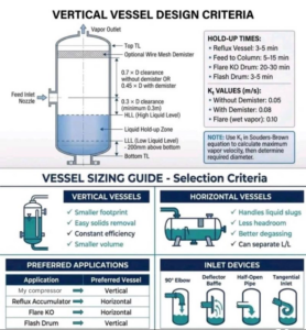
Thu thập dữ liệu quy trình bao gồm tốc độ dòng chảy, mật độ, áp suất, nhiệt độ và thời gian giữ cần thiết (thường là 3-15 phút đối với trống cấp liệu, 20-30 phút đối với trống KO bùng phát).
Chọn hướng: dọc cho dấu chân nhỏ hơn và diện tích tách biệt không đổi; ngang cho sên lớn và khử khí.
Kích thước bồn đứng
Tính đường kính bằng cách sử dụng vận tốc hơi tối đa từ phương trình Souders-Brown: v=Kt/sqrt((ρL−ρV)/ρV), trong đó Kt là 0,05-0,08 m / s (thấp hơn mà không có bộ khử sương).
Tiêu biểu Kt: 0,08 m / s với bộ khử sương, 0,05 m / s không có; Giảm xuống 0,7-0,8 đối với tạo bọt hoặc máy nén.
Chiều cao tổng LLL (~ 0,2 m), thể tích giữ, khe hở đầu vào (0.3D phút), vòi phun và khe hở trên cùng (0,7D không có bộ khử mù, ít hơn).
Kích thước bồn nằm
Sử dụng thử và sai: ước tính thể tích chất lỏng là tổng cộng 60%, giả sử L / D (3-5), đường kính tính toán từ D=sqrt(4Vliq/πL/D).
Đảm bảo không gian hơi cho phép Kt=0.08 m/s; HLL ≤80% đường kính, không gian hơi tối thiểu 0,3 m.
Thêm khởi động cho chất lỏng-lỏng nếu pha nặng <20% thể tích; kích thước khởi động D ≤0,5 tàu D.
Độ dày của bồn
Sau khi định cỡ hình học, tính toán độ dày vỏ với ASME UG-27: t=PR/(SE−0.6P), trong đó P = áp suất thiết kế, R = bán kính bên trong, S = ứng suất cho phép, E = hiệu suất chung.
Bao gồm phụ cấp ăn mòn (tối thiểu 1,5-3 mm) và xác minh đầu, vòi phun.
Quy tắc ngón tay cái
-
Tỷ lệ L / D: 2,5-5 cho bồn đứng; 3-4 phổ biến.
-
Bộ khử sương làm giảm đường kính bằng cách cho phép vận tốc cao hơn nhưng tránh trong các dịch vụ bám bẩn.
Luôn xác minh với mô phỏng chi tiết hoặc nhà cung cấp để thiết kế cuối cùng.
Sizing a process separation vessel is more than selecting a diameter and length.
It is about ensuring stable phase separation, operational safety, and process reliability.
Efficient vapor–liquid separation while maintaining adequate residence time.
⚙️ 1️⃣ Vertical vs Horizontal Vessels — Selection Criteria
Choosing the right orientation is the first engineering decision.
🔹 Vertical Vessels
Common applications:
• Compressor KO drums
• Flash drums
• Scrubbers
Advantages:
• Smaller plot space
• Easier solids removal
• Better for low liquid volumes
🔹 Horizontal Vessels
Typical uses:
• Reflux accumulators
• Flare knockout drums
• Surge vessels
Advantages:
• Handles liquid slugs better
• Larger liquid holdup
• Improved vapor disengagement
In systems with fluctuating flow, horizontal vessels provide better stability.
📐 2️⃣ Vapor–Liquid Separation Design
Separation efficiency is often governed by allowable vapor velocity.
The Souders–Brown equation is commonly used:
Vmax = K × √((ρL − ρV) / ρV)
Where:
V_max = maximum vapor velocity (m/s)
K = empirical constant
ρL = liquid density (kg/m³)
ρV = vapor density (kg/m³)
Typical K-values:
Without demister:
K ≈ 0.05 m/s
With demister pad:
K ≈ 0.08 m/s
Demisters allow higher vapor velocities while preventing liquid carryover.
⏱️ 3️⃣ Liquid Hold-Up Time
Residence time ensures proper separation and stable downstream operation.
Hold-up time is calculated as:
t = V / Q
Where:
t = residence time (minutes)
V = liquid volume in vessel
Q = liquid flow rate
Typical design guidelines:
• Reflux drums → 3–5 minutes
• Process separators → 5–10 minutes
• Flare KO drums → 20–30 minutes
Longer residence times allow entrained vapor bubbles to disengage.
📏 4️⃣ Vertical Vessel Geometry
Proper level positioning is essential.
Typical guideline:
LLL ≈ 200 mm above bottom tangent line
This prevents solids accumulation and ensures proper drainage.
📊 5️⃣ Horizontal Vessel Sizing Approach
Horizontal separators are usually sized through an iterative approach.
Initial assumptions:
• Liquid fill fraction ≈ 60% of vessel diameter
• High liquid level limited to:
HLL ≤ 0.8 × D
Where:
D = vessel diameter
Vessel Volume Estimation
Total vessel volume:
V = (π × D² × L) / 4
Where:
D = vessel diameter
L = vessel length
The L/D ratio typically ranges between:
3 ≤ L/D ≤ 5
This balance ensures good separation while keeping fabrication practical.
🎯 Engineering Insight
Poorly sized separators often lead to:
• Liquid carryover
• Vapor entrainment
• Compressor damage
• Unstable downstream control
Effective separator design ensures:
✔ Proper vapor disengagement
✔ Stable liquid inventory
✔ Reliable plant operation
Because in process engineering, separation quality often determines plant reliability.
#ProcessEngineering #ChemicalEngineering #OilAndGas #ProcessDesign #PlantEngineering #SeparationTechnology
Chia sẻ

Ý kiến bạn đọc (0)